PoE IEEE 802.3af and IEEE 802.3at
PoE (Power over Ethernet) is the name of a number of methods that allow for powering network devices through UTP/FTP cables. This way it is possible to power devices such as cameras, phones, switches, access points, etc. In 2003, the IEEE established 802.3af PoE standard, upgraded to 802.3at in 2009. 802.3at distinguishes between the first type (prior 802.3af) and the second type with maximum transmitted power of 30 W, nearly two times higher. The second type is suitable to power cameras with high-power IR illuminators, IP telephones, small network printers etc.
Comparison of the two types of PoE:
| Feature/standard | 802.3af (802.3at type 1 ) | 802.3at type 2 (POE+) |
| Output power of power supply [W] | 15.40 | 30.00* |
| Minimum power available for the powered device [W] | 12.95 | 25.5* |
| Output voltage of power supply [V] | 44...57 | 50...57 |
| Supplying voltage available at the powered device [V] | 37...57 | 42.5...57 |
| Max current [mA] | 350 | 600 |
| Ethernet compatibility | 10BASE-T, 100BASE-TX and 1000BASE-T | 10BASE-T, 100BASE-TX and 1000BASE-T |
| Range [m] | 100 | 100 |
| Cabling | UTP/FTP min. cat. 3 | UTP/FTP min. cat. 5 |
*Some companies developed solutions that transmit power over all 4 pairs of UTP/FTP cables (e.g. Cisco's UPOE). They allow power supplies with output power up to 60 W, and the power consumption of the powered devices can reach 51 W.
Advantages of PoE technology:
Depending on the location in the transmission path where the power supply is combined with the data, the power-injection devices can be divided into 2 groups: PoE switches (endspam) and PoE adapters (midspam).
 POE1601P
The POE1601P is a 16CH PoE Switch which is designed for the growing popular IP surveillance systems, this Gigabit 802.3at PoE working as central management of remote power control and IP camera monitoring.
Check detail
 POE2401P
The POE2401P is a 24CH fast Ethernet Power over Ethernet (PoE) switch which has twenty four 10/100BaseTX ports, and with additional two Gigabit (TP/SFP Combo)RJ45 ports for NVR and network connections.
Check detail
The power supply unit may implement both or just one of the PoE types, while remaining compliant with the standard. So, the powered device must therefore support both modes, however, as it turns out in practice, not all end devices are fully compliant with the standard. This may be the reason for the lack of compatibility with some PoE power supplies.
Wiring diagram for a PoE switch (endspan) and an 802.3af (802.3at type 1) powered device. Option A - violet color, option B - yellow color.
Wiring diagram for a PoE injector (midspan) and an 802.3af (802.3at type 1) powered device. Option A - violet color, option B - yellow color.
Wiring diagram for a PoE switch (endspan) and an 802.3at type 2 (PoE+) powered device. Option A - violet color, option B - yellow color.
Wiring diagram for a PoE injector (midspan) and an 802.3at type 2 (PoE+) powered device. Option A - violet color, option B - yellow color.
Testing procedures and classes of powered devices
PoE standard has been optimized for safety. In addition to a safe voltage range, the devices must communicate according to established procedures. Before providing the supplying voltage, the PoE power supply unit tests the connection. The current is limited to milliamperes and is applied to determine the actual type of the PoE implemented in the powered device (with the help of characteristic resistance of about 25 kΩ used for this purpose in the device). In addition, this procedure allows for checking the continuity of the line.
Optional classification of equipment compliant with 802.3af standard provides useful information about its power requirements. It is based on the measurement of the current flowing when testing the connection. The equipment is classified as follows:
| Class | Output power of power sourcing equipment (PSE) [W] | Power consumed by powered device (PD) [W] |
| 0 | 15,4 | 0,44 -12,95 |
| 1 | 4,0 | 0,44 - 3,84 |
| 2 | 7,0 | 3,84 - 6,49 |
| 3 | 15,4 | 6,49 - 12,95 |
| 4 | 30 | 12,95 - 25,5 |
Devices compliant with 802.3at also communicate with one another using Layer-2 power management protocol for enhanced power allocation, LLDP-MED (extended version of the protocol for auto-detection of devices). With such communication it is possible to determine the actual power demand with accuracy to 1.11W. The power supply unit forwards the information on the demand for power at regular time periods.
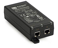
802.3af Power Supply
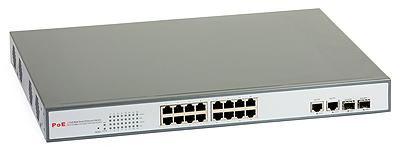
16CH PoE 802.3af Switch
Non-standard solution - passive PoE
Wiring diagram of a passive PoE injector and powered device
Passive PoE transmits power through selected conductors of UTP/FTP cable. The supplying voltage can be connected directly to the powered device or converted by a special adapter. There is no communication between the power source and the powered device - the power is provided continuously. The wiring is usually made according to option B of IEEE 802.3af (use of free pairs 4/5 (+) and 7/8 (-) in 10/100 Mbps Ethernet networks).
There are power devices that can operate in Gigabit Ethernet networks. They use transformers that enable transmit power along with the data (like in 802.3af option A). It should be noted that passive PoE solutions are not compatible with the 802.3at standard and are not recommended for use in professional networks.
An example of passive PoE solution in a CCTV network
Get My Latest Posts
Subscribe to get the latest updates.
Your email address will never be shared with any 3rd parties.
Tags: PoE, PoE IP, PoE Switch