Wiring the wired PIR motion detector
Even there is manual for most of wired PIR motion sensor, many customers (or users) still can't get the clear idea on how to wire the wired PIR Motion Detector.
Herein this tutorial will show you how to wire the wired PIR Motion Detector.
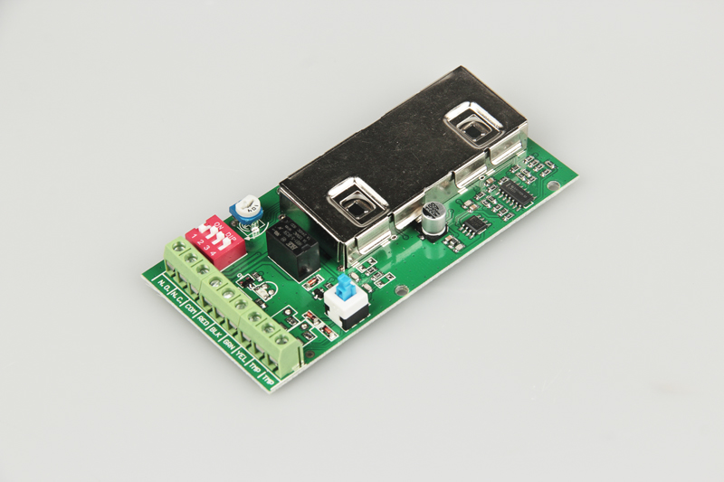
1. Open the cover of your PIR Motion Detector, then typically you will see the main-board as below:
TAMPER: This is a tamper protection for wired PIR. Normally it's a N.C. relay output. It provides the protection of wired PIR. If user connect it to zones of alarm panel, when people try to open the cover of the PIR, then the alarm will be triggered.
+12V GND: This is the power supply of PIR Motion Sensor, you can either connect to DC power from AC/DC adapter or connect to +12V output of alarm panel.
With the power supply of +12V, then the PIR can not work. Normally PIR can work wide-range DC power from 9V to 16V.
ALARM: This is the alarm output for PIR, it can provide N.O. (Normal Open) or N.C. (Normal Close) signal to alarm panel.
(Herein For VS-YH400, The default setting is N.C (Normal Close) output.
2. Wiring the cable from alarm panel.
a. Using cables (wires) connect the tamper to one of zones of alarm panel (This is an optional connection).
b. Using cables (wires) connect the +12V GND to +12V output of alarm panel or AC/DC adapter.
(Normally, Red wire is positive (+12V), Black wire is Negative (GND).
c. Using cables (wires) connect the ALARM to one of zones of alarm panel.
Connection for tamper and power are fixed for wired PIR and most of wired sensors.
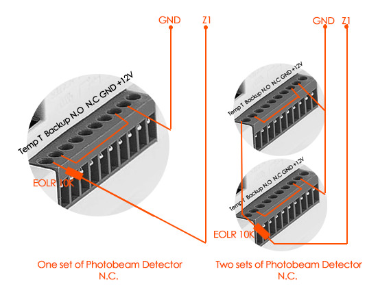
(Note: R1 is EOL Resistor, AUX is the power supply)
3. What's the EOL Resistor ?
EOL Resistor is end of line resistor, it must be installed (connect) to the end of wired detector.
Many alarm panel manufacturer may installed (connect) the resistor on the zones as default, it's only for testing.
The function of EOL resistor is to prevent the intruder cut the cable (wires) or short circuit the cable (wires).
4. Check the connection
After you finished the connection (wiring), it's better to double check the connection before turn on the alarm panel or PIR.
If the connection is correct, using muti-meter, you can check the resistance between tamper is 0, and the voltage between +12V and GND is +12V voltage, between ALARM, there is a specific value of resistance.
More information about wiring PIR Motion detector: https://burglaryalarmsystem.com/product-news/wire-pir-motion-detector-to-wired-alarm-system.html
5. Example of wiring PIR motion sensor


Red wire: +12V, Black wire: GND, Yellow: Zone 1, Green: COM.